Induction motor accounts for more
than half of the industrial load and are responsible for the poor power factor.
The power factor of an induction motor varies with the load on the motor.
Lightly loaded motor has a very poor power factor. Poor power factor results in
reduced capacity of transformers, cables and other equipments and are also
responsible for higher power losses because of increased current flow. They
also cause additional voltage drop.
Motivation for power factor improvement:
Utilities usually encourage the
consumers to improve the power factor of their installation by incorporating
power factor based penalty/rebate in the power tariff structure.
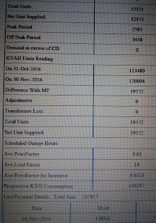

Figure shows the Electricity Bill of a Hotel for the month of Dec 2016. The premises, which is fed from 11 kV, is having an average power factor of 0.63 (as can be seen in the picture) for which the consumer has to pay a penalty of 28,759 INR ( a hefty amount indeed, for sheer casual approach)


Power factor may be billed as
one, or a combination, of the following:
1. A
penalty for power factor below a set limit. The penalty goes on increasing as
the power factor goes down,
2. A
rebate for keeping the power factor above a given value,
3. A
charge on monthly Reactive power (kVAr), and
4.
A flat charge for the maximum demand
recorded during the billing period in terms of apparent power (kVA).
Power factor improvement using Static Capacitors:
Static capacitors are among one
of the commonly used solutions to improve the power factor. They may be
provided on each individual induction motor or on the main bus bar depending upon the
consideration for cost, effectiveness, ease of operation etc.
Automatic Power Factor
Controllers (APFC) are employed on the main bus bar and helps to improve the overall
power factor of the establishment. Capacitor banks on networks with harmonics
may produce resonance. So special care should be taken while installing
capacitors on such circuits. The capacitance bank of the APFC is divided into
steps because the load may vary during the day. If the capacitor bank rating is
200 kVAr and 8 steps are available in the controller, then the step size of the
APFC is 25 kVAr. A simple APFC consists of similar step size.
Key elements of a small APFC:
Small APFCs are usually wall
mounted. The key elements of any small APFC are:
1. Power
Factor Controller,
2. Capacitor
bank,
3. Auxiliary
transformer,
4. Contactors,
5. Thermal
cut off switch,
6. Fans
for cooling,
7. Bus
bars, and
8. Circuit
Breaker (optional).
The Power Factor Controller provided inside the APFC automatically maintains the power factor (p.f) of the premises at a set value. It senses the power factor based on the input current and voltage. The controller has both auto and manual mode for switching the capacitor steps. In the auto mode, the controller automatically switches the steps to maintain the set power factor. In the manual mode, the operator is able to switch the steps. On failure of supply, all the capacitors are switched out. On restoration of power supply, the capacitors are switched on according to the load requirements. The controller has the following features:
1. The
pre-set value for automatic p.f correction is adjustable between 0.9 lag to
0.95 lead.
2. Facility
to manually set the power factor between 0.8 lag to 0.9 lead,
3. Adjustable
step switching timing,
4. Indicators
for capacitor steps connected, system p.f, set p.f, and other parameters.
The controller automatically
cycles the capacitors on a first on/first off basis so as to ensure equal usage
of each capacitor. The step switching time is provided to ensure a capacitance
step/unit is discharged before its switching to reduce the inrush current.
APFC does not operate when the
thermal cut off switch is ON. This switch is a temperature sensitive switch
which shuts off the power supply to the APFC when the temperature inside the
enclosure exceeds the pre-set temperature limit. In this case only the fans
provided for cooling operates. As soon as the temperature becomes normal, the
APFC unit again starts functioning.
To disconnect the APFC from the
network, circuit breakers are preferred over fuses. A current transformer (CT)
of proper specification has to be used so that it monitors both the load
current and the APFC current. The CTs usually used have a secondary current
rating of 1 or 5 A and burden of 15 VA. The rating for primary ratio is so
selected that the CT can handle the total line current i.e. load and of APFC
current along with the transients during starting. When connecting the CTs, the
secondary of each CT should be short circuited otherwise the CT may be damaged.
APFC units are built for indoor
operations and hence should be well protected from dust, moisture and
temperature. The APFC unit should be kept in a well ventilated space.
Some of the checks while Installing an APFC:
As an electrical engineer engaged
in installation of electrical equipments and substations, one has to make sure
that the transportation of APFC was safe. This can be done by checking the
packing of the unit. After removal of packing visually inspect the exterior and
interior of the APFC. Any loss or damage during the transportation should be
immediately reported to the manufacturer or their representative. The APFC unit
comes with the instruction manual and wiring diagram which must be referred
while installing the unit.
Careful handling is also necessary
during the installation process also. The equipment has usually two nameplates,
one outside and the second one inside the enclosure. These nameplates carry the
necessary information like nominal voltage, frequency, APFC capacity etc which
are very useful while installing.
All Automatic Power Factor
Controllers (APFCs) are full factory tested. Separate earth connection should
be provided to each APFC. All cables, wires and switchgear should be rated 1.5
times higher than the nominal current rating of the APFC and should be well
coordinated with current rating of the back-up fuses.
Working with an APFC:
While working with electrical
equipment, one has to be careful. The case is the same for APFC. Do not attempt
to work on a live APFC. After switching off the power supply to the APFC,
always wait for 5 minutes before working on the unit (by the time the power
capacitor gets discharged). Always verify that the capacitors are discharged.
AC capacitors are charged at a higher voltage than the nominal network voltage.
Always wear protective hand gloves and eye-protection while working on
electrical installations. To ensure safe access, the power supply of each
individual APFC must be isolated before opening. Check for residual voltages,
because of capacitor, before working inside the APFC.
The blog seems to share interesting tips transmission holding fixture, I like this information looking for an extra large automatic transmission holding fixture. Maybe I will share with facebook group friends about this blog.
ReplyDelete